
I have been considering automating a 2X6 antenna switch using the Broadcast Antenna Selection Data from N1MM+ (which I may refer to as simply N1MM from here on). Most Ham Radio contesters use N1MM+ for contest logging and many are now using it with two radios in a Single-Operator-Two-Radio (SO2R) arrangement.
N1MM Broadcast Data for Antennas
N1MM can send packets containing antenna information. I call this Antenna Select Data (ASD), which is not the same as Band Data. Band Data simply specifies the Band a radio is currently operating on. ASD provides the number of the antenna connected to a radio. Antenna numbers come from the Antenna tab in the N1MM CONFIG dialogue. Using ASD instead of Band Data allows the use of several antennas per Band and Several Band per antenna. This is a great fit for my station where I have multiple antennas, with some being multiband antennas. Just knowing what band a radio is on does not tell me which antenna to use.
The 2X6 Antenna Switch
A 2X6 antenna switch, sometimes called a Six Pack, allows selection of any of six antennas to be connected to either of two radios. The switch I am using was custom built by Mike K4GMH, a fellow member of PVRC. Similar commercial switches are available. My 2X6 switch actually consists of two boxes. The Controller Box, is used for connecting the two radios to the logic for antenna switching. The Controller has 6 LEDs on the front for each radio, to show the operator which antennas are currently connected to the radios. The other box, the Relay Box, contains the relays and the antenna connectors for antenna selection.
The Controller has a 4-wire data input for each of the two radios. N1MM provides the antenna numbers which are converted by an Arduino Nano ESP32 to drive the 4-wire ports. My 2X6 switch was originally designed to use Band data to select one antenna-per Band. To use the N1MM Antenna Select Data, the codes provided by N1MM are converted to select the desired antenna on the Relay box.
N1MM Antenna Table
The N1MM Antenna Table is shown below. I have created several antennas and indicated the Bands for which each can be used. Using ALT-F9, you can cycle through all antennas available for the Band a radio is currently using. More information on the N1MM antenna table can be found here. While I have configured 8 antennas in the Figure, the 2X6 switch can only use six Antennas, number 0-5.

The N1MM Antenna Table is configured with your Antenna setup. Each antenna has entries in the table for antenna number (Code 0-5) and the set of compatible Bands. Once the table is populated, this is the fixed antenna mapping, If you use N1MM in SO2R mode, as I do, logic is included to avoid trying to connect the same antenna to both radios, or using an antenna that is not compatible with the selected Band for that radio.
Protoype Components
The protoype for automating the switch consists of a Wifi-connected Arduino Nano ESP32 and a logic level shifter board. Data outputs from the Nano use 3.3 volt logic. The level-shifter board is included to convert to the 12-volt logic levels needed by my 2X6 switch.
A photo of the rough prototype is provided below. In this case, Radio #1 is using Antenna #3 and Radio #2 is using Antenna #1.
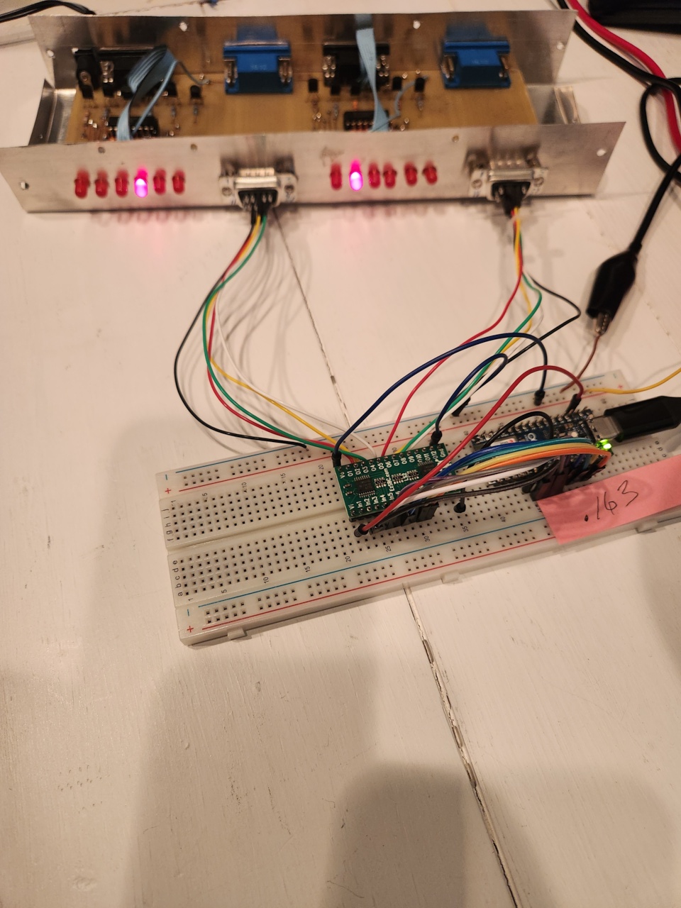
The photo below shows a better shot of the Arduino and Level Shifter Boards. Both of these will be integrated into a chassis with connectors to hook-up to the 2X6 Switch Control box.

Selection of Antennas
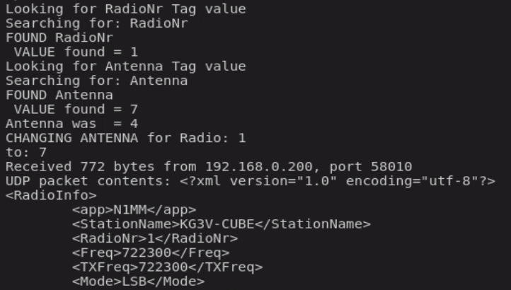
In N1MM, using the LOG window for either of the two radios, you just press ATL-F9 to cycle through available antennas. Only antennas that have been designated as usable on the current Radio Band are made available. If an antenna is already in use by the other radio, it is NOT available for selection for this radio. The text display below shows a debugging screen depicting the antenna selection process.
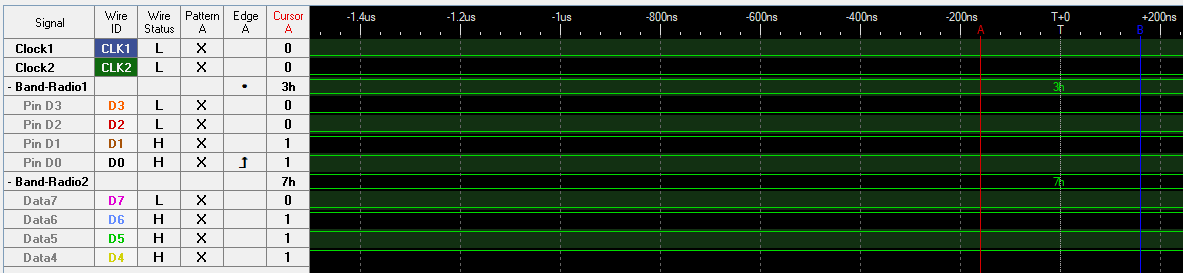
If you really want to get into the details, the following Figure shows a logic analyzer sweep of the two 4-wire antenna interfaces. In this case, Radio #1 is using N1MM Antenna #3 and Radio #2 is using N1MM Antenna #7 (which I have mentioned is not really allowed. Only antennas 0-5 can be connected using this switch.)
That is all for now. I have the code running and just need to get to work on a PC board and a chassis to house the Nano and Level-shifter boards. If you have any interest in, or questions about this project, please drop me a comment.

Hi Tom, I came across your blog and really enjoyed your detailed ham radio write-ups. I’m Emily from PCBWay, and I’d love to sponsor one of your future projects with free PCB prototyping. In return, we’d appreciate a brief review of your experience. Would you be open to it?
Thanks very much for your offer. I do not currently have any new design ready for prototype PCB, but will consider your offer when I do. Any review I would provide would be a completely honest review of my experience.
Hi Tom, thanks for getting back to me and we appreciate your willingness to collaborate on your future projects. Whenever you’re ready, feel free to reach out to me anytime at marketing@pcbway.com. I’m looking forward to collaborating in the future.