*** Updated 4 Sept 2025 *** 2nd Protoype section updated, completed and tested
Automated Antenna Selection with N1MM+
This Page covers development of the KG3V Antenna Decoder (AntDecoder). The goal of the project is to control antenna switching equipment, such as a 2-Radio X 6-Antenna (2X6) “Six Pack” switch, in a Single-operator-2-radio (SO2R) Contest Station using a PC with N1MM+ Contest Logging Software. Two 4-bit switch-control ports are provided for driving the 2X6 switch. Status Updates will be made to the Main section of this Blog and this Page will provide an ongoing summary of the Project (updates at the end).
PROJECT BACKGROUND
The N1MM+ Contest Logger (and some similar Applications) provides Antenna Selection Data (ASD) in UDP Broadcast data streams. The “Radio” packets are used to provide a steady update stream of Radio-number and Antenna-number mappings. When using N1MM+, the Antenna-number corresponds to the numbers in the CONFIG-Antenna tab. Using the N1MM+ Antenna table allows N1MM+ to control the selection logic. This does not allow the same antenna to connect to both radios, and supports both multiple antennas per Band and multiple Bands per antenna. This simplifies the design of the software while providing all of the functionality available from N1MM+.
Design Concept
The N1MM+ UDP stream is broadcast through a WiFi LAN connection. Using standard Arduino libraries, the AntDecoder connects to the LAN and receives the UDP packets sent by N1MM+ to its IP address. The AntDecoder decodes this data, and provides the encoded 4-bit ports for driving the particular 2X6 switch.
The AntDecoder hardware uses an Arduino Nano ESP32 microcontroller board. Software for this board is designed using the standard Arduino IDE. The AntDecoder can be physically located at the 2X6 switch, using only the WiFi connection to N1MM+ on the Shack computer. Since the Broadcast datastream is sent using UDP packets, there is NOT a guarantee of successful delivery. To improve reliability of the link, the AntDecoder will send a telemetry stream that can be captured to display the Radio-antenna mappings and to detect and report any error conditions (like receipt of an invalid antenna number).
First prototype Testing (using hardwired connection and OTRSP)
During this initial design stage in 2021, testing of the concept was done using a modified DXDUSB PC Board (data found on this blog) and the N1MM+ OTRSP serial data stream. This approach has now been abandoned in favor of the WiFi-based approach and a new set of hardware. That design will be documented below. Here is a photo of the initial AntDecoder OTRSP prototype:
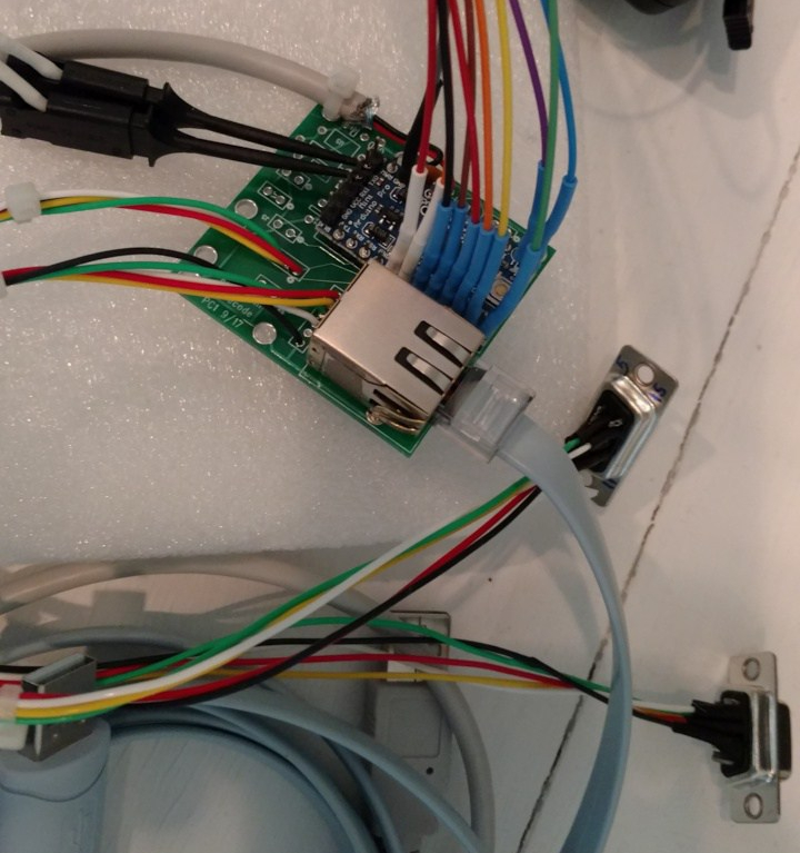
A digital Logic Analyzer showed that the Antenna Select lines were being driven from the N1MM+ code. Driving my 2X6 switch required converting the driver lines to 12-volt logic. This was done using an inexpensive level converter board readily available on eBay. Here is a picture showing the conversion prototype and successful driving of one of the switch ports:

2nd Prototype – WiFi connection and Arduino Nano ESP32 Board
********* Sept 2025 update ***************
A 2X6 antenna switch has been connected and tested, and it seems to work fine. Software has been updated to convert the Antenna Numbers from the N1MM+ Antenna Table to the BCD codes needed to drive the 2X 6 switch. The switch being used was originally designed to be driven by Band Data from two K3 radios. Data conversion by the ESP32 provides the codes for Antenna Number to drive the switch.
Next up is to do some testing in a contest. In parallel, I am starting a new PC Board layout to incorporate the ESP32 Arduino Nano and the logic level conversion hardware needed to drive the 12 v inputs to the switch.
Some additional detailed posts will be coming soon, in the Main KG3V page.
