
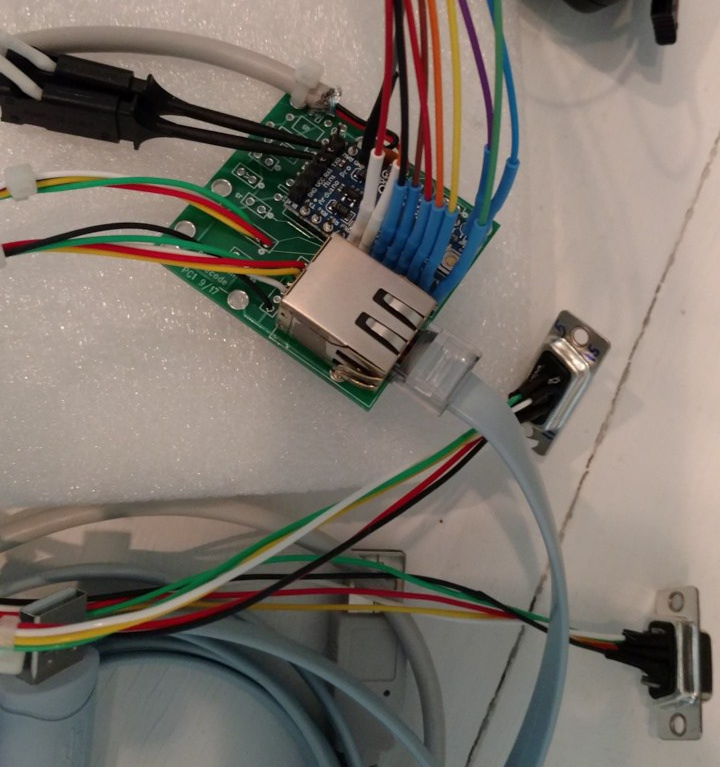
This weekend, I finally got a chance to assemble and test a prototype PC Board for the AntDecoder. The board and the software worked fine. The only issue is that I need to add output buffers to the Arduino lines that drive the two BCD ports for the Antenna Switch. The switch uses 12-volt logic and the Arduino is a 5-volt board with 5-volt logic. It is not possible to interface an Arduino output to logic levels above 5-volts.
Here is the initial prototype board that is being used for software development.
The interface between the Arduino and the Antenna Switch needs to be open-collector (or open-drain), to support conversion to higher-voltage logic. This will also be compatible with the outputs of the Elecraft K3 Band Data, which uses open-drain outputs. The switch I am using has pull-up resistors to 12-volts DC on the BCD input lines.
Here is a prototype of an interface with switching transistors and open-collector outputs
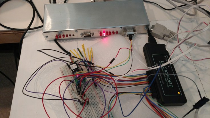
Not pretty, but it works. So the final step will be to either add the transistor switches to the outputs on this PC Board, or create a second PC Board that includes the switches. I will also be looking for a commercially-available converter board. There might be something that is used to convert TTL circuitry to drive relays. The addition of the output switches should take a couple weekends. I hope to have something finished in the mid-Feb 2018 time frame.

Good news!