
I have decided to revive a project that I started over a year ago, but had put on hold. My Station is setup for SO2R operation but I do not have automated antenna switching in place. I have 3 or 4 antennas, depending upon the contest, and manually connect and disconnect them as the contest proceeds. That is not a strategy for Contesting success, and it must be improved. Having access to all antennas throughout the contest will allow me to adjust in real-time to changes in propagation and gives me a better chance to catch short or unexpected Band openings.
My current QTH is on a fairly small lot, about 3/4 of an acre, so the HF antennas are closely co-located for use in SO2R. That is one reason I had abandoned this project in the past. But I now have a new location with more land, where I will be constructing a Station. That is the primary target of this project.
Initial Project Plans
The initial project will use a Wireless device to extract the Antenna switching information from N1MM and provide the control lines to configure the antenna switch. My antenna switch is a 2X6 Switch, similar to those made by several manufacturers. It just needs a 4-bit digital control input for each radio, to tell it how to connect the antennas. N1MM provides Antenna information in the serial UDP Broadcast Data stream that it outputs to my Network during the Contest. You can read more about that here.
The UDP Broacast’s Antenna information is contained in the Radio Info packets. I like to refer to this as Antenna Select Data (ASD), which differs from Band Data. This powerful difference allows you to have multiple Bands-per-antenna and multiple antennas-per-band. A simple table in the N1mm+ Configurer is used to define the mapping between bands and antennas. When operating on a Band, a Function Key allows you to quickly cycle through all antennas that are usable on taht Band. This has been described in more detail in some of my prior Blog posts and in the excellent N1MM+ documentation.
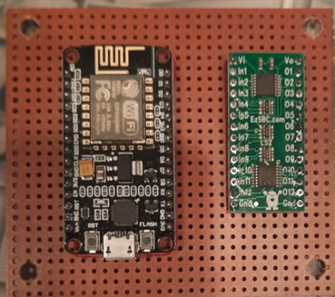
My initial plan is to use the ESP8266 Node MCU as the wireless device that will control the switch. I have done some experimenting with it, and the initial prototype seems to work, but I need to add level-shifting, as it takes 12-volt switching logic. The attached photo shows the Node MCU and a level-shifter board that I purchased that I am hoping will provide the proper signal interface.
The Development Approach
The Arduino Integrated Development Environment (IDE) can be used for developing code for the Node MCU. My plan is to use that, since I have experience with it already. The node MCU also has the ability to use other programming languages, but I am trying to avoid going that route. I had an earlier concept for this switch using just an Arduino and N1MM serial data from a COM port (blog article is here). This proved to not be the best approach for me, so I am now looking at using the Ethernet Broadcast data instead, and the Node MCU device.

Leave a comment