
I have been looking at implementing a Driver for a 2X6 (2 radios and 6 antennas) antenna switch, driven by N1MM for a couple years. I finally decided to design and build a PC Board for the Driver. I have done several posts about this and did not get that much interest. But, since I need this for my SO2R contest station, I decided to go ahead with the design. I now have a working PC Board that should be able to drive my 2X6 antenna switch from the N1MM+ Antenna Config table.
The PC board contains an ESP32 processor and ICs that generate the switching logic and perform level shifting. The ESP32 provides 3.3V signals. These are converted to the necessary levels for the 2X6 switch being used. In my case, the levels are shifted to 12 VDC to drive the antenna switching relays. I will refer to this as the “WASP” PC Board.
2X6 Switch Driver Background
I have a 2X6 antenna switch that is intended to be driven by Two Antenna decoders. The switch is for 2 radios and allows each to connect to any of up to 6 antennas. My 2X6 switch was designed to be driven by decoders that connect to Elecraft K3 radios. So, as a starting point, I assumed that the decoder values are the same as those that are provided by a K3 radio. The K3 provides antenna values that are Band-specific. Here is the basic table of K3 antenna values:
| BAND | B3 | B2 | B1 | B0 | DEC |
| 160 | 0 | 0 | 0 | 1 | 1 |
| 80 | 0 | 0 | 1 | 0 | 2 |
| 60 | 0 | 0 | 0 | 0 | |
| 40 | 0 | 0 | 1 | 1 | 3 |
| 30 | 0 | 1 | 0 | 0 | |
| 20 | 0 | 1 | 0 | 1 | 5 |
| 17 | 0 | 1 | 1 | 0 | |
| 15 | 0 | 1 | 1 | 1 | 7 |
| 12 | 1 | 0 | 0 | 0 | |
| 10 | 1 | 0 | 0 | 1 | 9 |
| 6 | 1 | 0 | 1 | 0 |
Since my decoder will be driven by N1MM+, I do not want band-specific antenna values. I just want antenna number 0, 1, 2, 3, 4, 5. My driver will do the necessary conversion from N1MM+ antenna numbers (from the Config–>Antenna table) to antenna numbers 0, 1, 2, 3, 4 or 5.
Using the N1MM+ antenna numbers instead of Band-specific number allow me to have multiple antennas-per band or multiple bands-per-antenna. Large contest stations often have totally band-specific antennas. Those of us with smaller stations often have to use multiband antennas.
Architecture of the 2X6 Driver
My 2X6 Driver sits in between N1MM+ and the 2X6 antenna switch (aka the Six Pack). N1MM+ is running on my min station computer and is connected to two radios. At present, the two radios are an ICOM IC-7610 and an ICOM IC-7600. An ESP32 processor (Arduino nano ESP-32) Is connected to the station PC via WiFi. N1MM+ has been configured to send data to the ESP32 using WiFi. The ESP32 receives Radio Number and Antenna number data from N1MM+ via WiFi. The Antenna number codes are received for Radio1 and for Radio2 and are converted to the correct values for driving the switch. The 2X6 switch commands are then sent to the switch by hardware from the WASP PC board.
The 2X6 Switch Driver WASP PC Board
The WASP PC Board includes the ESP32 processor and level shifters. The bulk of the effort in this design was, of course, the software. The software was created with the basic Arduino toolkits and used the PlatformIO programming interface. If you have not tried platform.IO and you do a lot of Arduino development, you are missing out on a great toolset.
The Version 1 PC Board is shown below. The green LEDs indicate the current antenna code for each of the 2 radios. In addition to the two radio ports, there is a third set of I/O lines that are brought out for potential future use. The large jumper wires that can be seen in the photo are used to enable/disable the LEDs. I did not have nice 2-pin jumper blocks handy, but that is what would really be there in a functioning board.
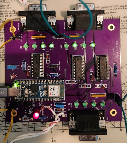
Coming Soon – Fully Functional 2X6 Antenna Switch Driven from N1MM+
I have been working on this for a long time. Fortunately, once I built up the PC board, it worked perfectly the first time. Now I am ready to connect it to the 2X6 Antenna switch. Once I do that, I will update this post with the results.


Leave a Reply